|
|
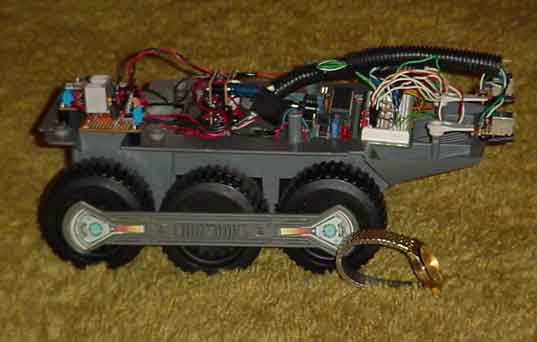 This page documents my attempt to build an autonomous, indoor robot and hopefully explain its construction in such a manner as to assist other beginners with their robotics projects. My bot actually began as a modified 4wd truck I purchased at Walmart, but the truck platform was discarded when I came upon a used Big Trak toy from the 1980s. Since this project is actually the software & electronics test bed for an autonomous vacuum cleaner project thats always fascinated me, its much more useful to utilize a platform like the Big Trak due to its superior size, built in optical encoder and differential steering. Its construction is very similar to what I had envisioned for the vacuum cleaner, so the transition from floor covering robot to robotic vacuum will be much easier.
It can be anything you want, provided you can both assemble and control it. This one, as I said before is based on an old, programmable toy from the 1980s called the "Big Trak" The Big Trak is a 6 wheel, 2 wheel drive computerized toy from Milton Bradley. It was originally designed to store a limited number of commands (forward, turn, reverse, fire "photon cannon" etc..) and then execute them on demand. Some of the features that make the Big Trak attractive for a project like this are:
A built in optical encoder, with room for a second. This allows basic distance measurements and therefore some degree of dead head navigation. The spot for the second one is molded over, looks like it could have been a last minute design change. A large battery box, perfect for allot of "AA" size ni-cads. (It originally contained 4 "D" sized cells.) The motors and drive train are pre-installed. At about 8.5 X 13" its a large platform for an indoor robot. The gearbox features a unique magnetic clutch mechanism which allows the drive wheels to turn at exactly the same rate. This is very handy as it tends to track straight ahead as opposed to yawing. The factory electronics (though of low quality) lend themselves to modification, eliminating the need to construct a h-bridge and wiring for the encoder, speaker and "photon cannon" There are also provisions for separate 6 & 9 volt power supplies for the motors and micro-controller. Since this is a test bed however, all the factory electronics were removed. No matter what youre looking for in the way of a platform, try Ebay first. There is a complete glut of toy and RC vehicles there (tanks, trucks, earth movers, fire trucks.. you name it) that would make great robotics projects for cheap.
The "brains" of a robot. There is a wide variety of cpu's avalible, from simple chips with onboard hardware and oscillator right up to embedded desktop systems complete with a hard drive. This one however is based around the PIC Microcontroller from Microchip.® The PICs strong suit is robotics and industrial automation, which makes it perfect for projects like this. Its cheap (less than $10.00 each) reasonably fast (This one, the 16F877 runs at 20mhz) and comes in a wide variety of configurations which allow it to be custom tailored to a particular application. (different onboard hardware, different packages, pin count, number of i/o lines, analog to digital converters, HPWM and so forth) The chip, programmer and programming software ("Mbasic Pro", the windows programming interface and compiler) are from Basic Micro 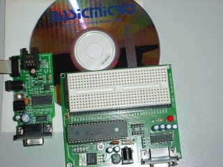
Their combo package comes with all the software, a solderless development board (breadboard) and a bunch of useful commands for running servos, controlling stepper motors, serial communications, I2C devices and so on which makes it easy to use and allows you to get simple things done without having to deal with Assembly Language and hardware nuances directly. Anything that falls outside the ability of MBasic can be done in ASM and commingled with the Basic code, so its kind of the best of both worlds, imo. There are also other, easy to use (even for the total novice) controllers with Basic Language software such as the Basic Stamp 1 & 2 by Parallax (very popular) and the ATOM, also available from Basic Micro. If youre like me your worst fear is buying something, not being able to use it thus suffering an expensive and demoralizing setback. Not to worry, even if you never programmed anything before in your life, you couldnt go wrong with any of these products, imo. This is probably the most expensive part of building a bot, although you can do this practically for free if you feel like learning low level programming languages like "C" and ASM. They are nearly overwhelming for the beginner, but they are cheap and readily available. You can even get a A Book that comes with a programmer board and all the requisite software attached to the back jacket for less than $35.00! But its definitely going to be an uphill climb for beginners.
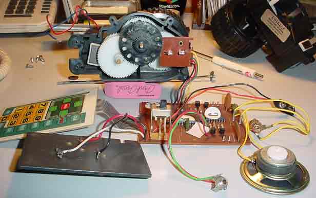
This is a view of the Big Trak gearbox (one half of it anyway) and all the factory electronics. There are various gears, half of the magnetic clutch, attached to the motor output shaft (the square magnet to the left of the gearbox) the keypad, main circuit board, speaker, light bulb socket (for the "photon cannon") phonojack (for a trailer accessory that was available separately) power connectors and the optical encoder.
The optical encoder (the small, square assembly to the right of the large gear) and the motors are the only electrical components that will be retained. The encoder is basically just an infrared led that shines through holes in the drive gear and is picked up by a photo transistor on the other side. As the gear rotates, the beam is interrupted. By counting these interruptions a distance measurement is made, it basically acts as a simple odometer. More complex encoders might incorporate a second IR led & photo transistor to determine the direction of rotation as well. "diagram to follow shortly"
DC Motors are pretty simple, when current is applied in one direction, the motor spins. When the polarity is reversed the direction of rotation is reversed. To be able to do anything useful its necessary for the Microcontroller to be able to operate the drive motors. Since the current a drive motor requires far exceeds what the PIC is capable of sourcing, a motor controller called an H-Bridge is used. An H bridge gets its name from the "H" pattern that forms around the motor in a schematic. They can be built with relays, transistors or power mosfets, there are also commercially available bridge driver chips which configure the necessary transistors or mosfets on a single chip. One of the best (and most widely used) is the L298 Bridge driver. The L298 can handle current to 2 amps per channel (4 amps total) and provides directional & braking control. It also has a "Current Sensing" feature that can provide feedback to the microcontroller indicating motor load. This is an especially useful way to detect a motor stall and consequently shut the current off. The complete drive circuit is shown below.
They fall into two categories, digital and analog. A Digital sensors output signal consists of 0s & 1s, which makes them easy to use with a microcontroller and simple to understand. Many are either on or off, logic 1 or logic 0. A microswitch "whisker" sensor is a good example of an on or off, logic 1 or logic 0 sensor. There is not a great degree of flexibility here though, so some digital sensors (like a digital temperature sensor for example) may output bits (0s & 1s) grouped into Bytes or Words. They may add bits to indicate negative numbers or to uniquely identify themselves on the buss. Analog sensors usually output a voltage thats proportional to their input. This is converted into bits to be used in a program by passing them through an analog to digital converter. The A/D converter is standard onboard hardware for many microcontrollers. It's important to keep this in mind when purchasing sensors and hardware.
They all function the same way, by bouncing beams of light off an obstacle and then measuring the amount that is reflected back. They also suffer from the same problems:
2) Poor reflectivity of some obstacles. (Like a black, fuzzy speaker box for example) One thing that can be done to minimize interference from ambient lighting is to get the light out of the visible spectrum by using Infrared (or near infrared) light.
That helps, but there is still a significant amount of infrared floating around to cause problems. To help distinguish light from the emitters its modulated (flashed) usually between 38 and 40Khz.
1 cycle per second is 1 Hertz, so 38 to 40 Kilohertz is 38 to 40 thousand times a second. There also must be a sensor capable of picking it up and ignoring other light sources. These typically include several stages.
2) A light sensor (usually a photo diode) 3) An amplifier. (because the signal from the sensor is pretty weak) 4) Another band pass filter. (this time its a piece of hardware that restricts frequencies other than the modulation frequency.) 5) A Comparator. (to establish a threshold value) 6) Usually a Faraday cage or some type of shielding. (to protect against electromagnetic interference) There are also assembled IR Receiver modules that do all this from places like Digikey, Mouser Electronics and Jameco. They are used in things like VCR remote controls and come optimized for a certain frequency. This bot will be using the LITEON remote control module, #LTM-9034 (Jameco part number: 176541) They are rated at 56.8 Khz.
Note: There is a big difference in performance between these modules. They were intended to sense IR light from a remote control 8 or 10 feet away and to be very forgiving in terms of ambient lighting conditions. These particular modules work very well, but I tried several other brands that were completely useless for a project like this. One brand apparently had a built in gain control circuit that attempted to compensate for different light levels. This would have worked great for an IR remote but skewed the output so wildly that its useless here because you dont know if youre 6" from a target in the dark or 6 from the same target in a brightly lit room. Fortunately they are cheap, so sampling different brands and mocking them up isn't a problem, but to avoid suprises light sensors should be tested under a variety of conditions. There is also a Spectral Sensitivity rating for IR sensors that allows them to be matched to the emitters. From 900 to 1000 Nm is common.
Light sensors can be further divided into two sub categories, Proximity sensors and Ranging sensors. Proximity sensors are usually digital and are intended to detect obstacles within a given distance. Example: "Yes or No, do you see an obstacle anywhere within 6" of the front of the bot?" The LITEON modules will function strictly as proximity sensors. Ranging sensors, like the Sharp GP2D12. (from Acroname or Digikey) not only report the presence of an object, but its distance as well. The downside to many ranging sensors is a minimum effective range (below which they dont work. It is possible to set them to sweep across the front of the bot to minimize this however) and skewed distance readings depending on the reflectivity of the obstacle. They also cost 3 to 4 times more than a generic sensor like the LTM-9034.
Hardware Pulse Width Modulation The 16F877 (as well as others) has onboard HPWM which allows it to rapidly toggle the state of a pin (low to high) and output the 56.8 Khz pulse thats needed to flash the IR emitters. Once HWPM is started it runs independently of the main program loop, leaving the PIC free to do other things. It can output different frequencies by varying the Period of a pulse and different voltages by varying the pulse's Duty Cycle. It can also be started, stopped or altered with software during program execution.
 For example, shortening the Period increases the number of pulses and raises the Frequency. (one pulse per second = one Hertz. A thousand pulses per second = a Kilohertz, etc..) The duty cycle is the high, on or logic 1 time of the pulse. If a pin sources 5 volts when its high (duty cycle = 100%) then toggling it rapidly from high to low with a 50% duty cycle will yield about 2.5 volts. There are limits to what can be powered directly with an i/o pin. For example, I think the 16F877 can sink (to ground) or source (power) a maximum of about 20 Ma per pin. (actually I am too lazy to get out the datasheet and look.) With MBasic HPWM is started, stopped or altered with a single command. Alternatively a 555 timer or other oscillator could be used to flash the leds. These are covered in "Timer, Op Amp & Optoelectronic Circuits & Projects" By Forrest Mims. (Radio Shack part# 62-5032) Actually the whole series is pretty good. Its invaluable to anyone who is new to electronics in general, lot of good stuff in there. More to follow...
 | |||||||||||||||||||||||||||||||||||||||||||